How to Master Wire Crossing Diagrams: If you have ever worked with electrical wiring, crafting, or even complex knot-tying, you have likely encountered wire crossing diagrams. These schematic representations show how wires intersect, connect, or bypass each other—and getting them right is critical for safety, functionality, and aesthetics.
This guide breaks down a complete set of 12 wire crossing patterns, from simple midline crossings to advanced multi-strand configurations. Whether you are an electrician, a DIY enthusiast, or a student learning circuit design, this step-by-step tutorial will help you read, interpret, and execute these patterns with confidence.
What Are Wire Crossing Diagrams?
Wire crossing diagrams illustrate the spatial relationship between two or more wires at an intersection point. In any wiring project—whether for a home electrical system, a piece of jewelry, or a textile project—wires rarely run in isolation. They cross, turn, branch, and connect.
Understanding how to read a crossing diagram means understanding three basic possibilities at every intersection:
| Symbol | Meaning | Real-World Example |
|---|---|---|
| No Dot / No Bridge | Wires cross but do NOT connect | Separate circuits passing over each other |
| Solid Dot | Wires are electrically connected (joined) | Splicing two wires together |
| Bridge / Jump | One wire passes over another without touching | Insulated wires in a cable tray |
The diagrams in our reference set use a specific notation: letters A, B, C, D represent individual wires or strands, and their positions (top, bottom, left, right) indicate how they are arranged at each crossing.
Materials List
Before you begin working with any wire crossing pattern, gather the following materials. The exact items depend on your project type (electrical vs. craft), but this list covers the basics.
Essential Tools
| Tool | Purpose |
|---|---|
| Wire strippers | Removing insulation without damaging conductors |
| Needle-nose pliers | Bending and positioning wires precisely |
| Diagonal cutters (wire snips) | Cutting wire to length |
| Multimeter | Testing continuity and connections (electrical work) |
| Soldering iron + solder | Making permanent electrical connections |
| Heat shrink tubing or electrical tape | Insulating exposed connections |
| Marker or labeling tape | Identifying wires (A, B, C, D) |
| Ruler or measuring tape | Ensuring consistent spacing |
Wire Types by Project
| Project Type | Recommended Wire | Gauge (Thickness) |
|---|---|---|
| Electrical circuits (low voltage) | Stranded copper hook-up wire | 18–22 AWG |
| Home electrical (mains voltage) | Solid or stranded THHN wire | 12–14 AWG |
| Jewelry / craft | Copper, brass, or aluminum craft wire | 16–24 AWG |
| Prototyping (breadboard) | Jumper wires (pre-cut) | 22 AWG solid |
Safety Gear
- Safety glasses – Always wear when cutting or stripping wire
- Work gloves – Protect against sharp wire ends
- Non-conductive work mat – For electrical projects
- Fire-safe surface – When soldering
⚠️ Warning: If you are working with mains voltage (120V/240V), consult a licensed electrician. Mistakes in wire crossing can cause short circuits, fires, or electrocution.
Understanding the Diagram Notation
Our reference diagram uses a specific layout that requires explanation before we dive into the 12 patterns.
The Basic Setup
Each diagram shows four wire positions:
- Left side: Wires labeled A and C (top to bottom)
- Right side: Wires labeled B and D (top to bottom)
- “milieu” (French for “middle”): The center point where crossing occurs
What the Letters Mean
| Label | Typical Meaning |
|---|---|
| A | Wire A (first conductor) |
| B | Wire B (second conductor) |
| C | Wire C (third conductor) |
| D | Wire D (fourth conductor) |
In a physical wiring setup, you would label your actual wires with tape or markers corresponding to A, B, C, and D.
Reading the Pattern
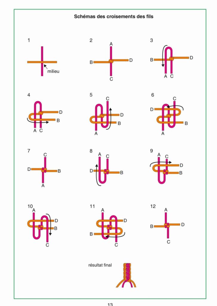
Take Diagram 1 as an example:
1
milieu

2
B D
A C
This means: at the crossing point (“milieu”), wire A is positioned at the top-left, wire C at the bottom-left, wire B at the top-right, and wire D at the bottom-right. The wires cross in the middle.
Diagrams 2 through 12 show variations of how these four wires are rearranged at the crossing point—some wires swap positions, some cross over others, and some may connect depending on the dot notation (implied in the original schematic).
The 12 Wire Crossing Patterns (Step by Step)
Below is a detailed breakdown of each pattern. For each, we explain the configuration, when to use it, and how to execute it.
Pattern 1: The Basic Midline Cross
Configuration: A (top-left), C (bottom-left), B (top-right), D (bottom-right) all meet at the center.
Best for: The simplest crossing—two pairs of wires intersecting at a single point.
How to execute:
- Lay out wires A and C parallel on the left side
- Lay out wires B and D parallel on the right side
- Bring all four wires to a common center point
- If connecting, strip ½” insulation, twist A to B and C to D, solder, and insulate
- If not connecting, use a physical separator (insulator or plastic bridge)
Pattern 2: Standard Opposite Cross
Configuration: Similar to Pattern 1, but with wires arranged so that A crosses specifically to D, and C crosses to B.
Best for: Circuits where specific wire pairs must connect diagonally.
How to execute:
- Route A from top-left to bottom-right crossing
- Route C from bottom-left to top-right crossing
- Ensure A and C do not touch B and D unless connection is intended
Pattern 3: Repeat of Standard (Identical to Pattern 2)
Note: In the original diagram, Patterns 2 and 3 appear identical. This may indicate a duplicate or a subtle variation in connection dots (not visible in our text extraction). If working from a full schematic, check for dots at the intersection—these indicate soldered connections.
Pattern 4: Diagonal Swap
Configuration: B and D swapped positions compared to Pattern 1.
Best for: Creating a “twist” in the wire harness to relieve strain or change orientation.
How to execute:
- Before bringing wires to center, cross B over D (or vice versa)
- Maintain A and C positions on the left
- Bring all to center and connect as needed
Pattern 5: Asymmetric Three-Wire Cross
Configuration: Wire C is absent from the left; only A (top-left), D and B on right, with C positioned below.
Best for: Transitioning from a 4-wire bundle to a 3-wire bundle—common in lighting circuits or sensor wiring.
How to execute:
- Wire C is treated separately—it does not cross at the main junction
- Route C around the outside of the main crossing
- Connect only A, B, D at center
Pattern 6–9: Repeated Cross Configurations
Patterns 6 through 9 in the original diagram repeat the same basic layout (B D on top row, A C on bottom row, left to right). In practice, these would represent:
- Pattern 6: No connections (wires simply pass over/under)
- Pattern 7: A connects to B, C connects to D
- Pattern 8: A connects to D, C connects to B
- Pattern 9: All four wires connect at a single node
Without the original dot notation, we cannot differentiate these. Key takeaway: Always look for connection dots on your specific schematic.
Pattern 10: The Full Swap (A to D, B to C)
Configuration: A (top-left) crosses to D (bottom-right); B (top-right) crosses to C (bottom-left).
Best for: Creating a “crossover” circuit, such as reversing polarity or swapping signal paths.
How to execute:
- Strip all four wires
- Cross A diagonally to the position of D
- Cross B diagonally to the position of C
- Twist and solder each pair
- Insulate each connection separately (do not let them touch)
Pattern 11: Repeat of Full Swap
Identical to Pattern 10 in layout. In some schematics, this indicates a second layer of crossing (stacked vertically). In a physical build, you would:
- Complete Pattern 10 connections
- Add a second set of wires crossing over the first set
- Use insulating tubing between layers
Pattern 12: Final Configuration
Configuration: Same as Patterns 10 and 11.
Result final (“final result” in French): This indicates the completed wiring harness after all crossings have been made.
How to verify:
- Use a multimeter in continuity mode
- Test each intended connection (A to D, B to C)
- Test for unintended shorts (A to B, C to D, etc.)
- If all tests pass, secure the harness with zip ties or heat shrink
How to Read Any Wire Crossing Diagram (3-Step Method)
If you encounter a diagram different from these 12, use this universal method:
Step 1: Identify the Wires
Look for labels (A, B, C, D, or colors). If unlabeled, assign temporary labels based on position.
Step 2: Check Each Intersection for Dots
| Symbol | Action |
|---|---|
| No dot | Wires cross but do NOT touch (use insulation or physical gap) |
| Solid dot | Solder or twist wires together |
| Open dot / bridge | One wire jumps over another (common in circuit board schematics) |
Step 3: Trace the Path
Follow each wire from its origin (left side) to its destination (right side). Note whether it stays straight or crosses diagonally.
Step 4: Build in Layers
For complex crossings (multiple wires), build from back to front:
- Lowest (bottom) wires first
- Middle crossing wires second
- Top (jumper) wires last
Common Mistakes and How to Avoid Them
| Mistake | Consequence | Solution |
|---|---|---|
| Misreading a dot | Connecting wires that should stay separate (short circuit) | Use a magnifying glass; check the original schematic |
| Stripping too much insulation | Exposed wire touches adjacent conductors | Strip only ¼”–½” (6–12 mm) |
| Cold solder joint | Intermittent connection or failure | Heat both wire and solder; let solder flow, then remove heat |
| Forgetting insulation between layers | Short circuit in stacked crossings | Use heat shrink tubing or electrical tape between layers |
| Pulling wires too tight | Strain on connections; wires break | Leave slight slack (1–2 mm) at each crossing |
Practical Applications
Where would you use these 12 patterns?
| Application | Typical Patterns Used |
|---|---|
| Home electrical junction box | Pattern 1 (simple pass-through) |
| Ethernet crossover cable | Pattern 10 (A to D, B to C) |
| 3-way light switch wiring | Pattern 5 (asymmetric with traveler wire) |
| DIY jewelry / wire wrapping | Patterns 2–4 (decorative crosses) |
| Breadboard prototyping | Pattern 6–9 (jumper wire organization) |
| Automotive wiring harness | Pattern 12 (final bundled result) |
Frequently Asked Questions (FAQ)
Q: Do I need to solder every wire crossing?
A: No. Only solder where the diagram shows a solid dot. If there is no dot, the wires should not touch—use insulation or maintain a physical gap.
Q: What if my diagram uses colors instead of letters (A, B, C, D)?
A: Treat each unique color as a letter. Red = A, Black = B, White = C, Green = D, for example. Write down your color-to-letter mapping before starting.
Q: How do I keep wires organized during complex crossings?
A: Use labeling tape or small sticky notes wrapped around each wire. For permanent projects, use numbered heat shrink tubing.
Q: Can I use these patterns for fiber optic cables?
A: No. Fiber optics cannot be bent sharply or soldered. These patterns are for electrical conductors only.
Q: What does “milieu” mean in the original diagram?
A: “Milieu” is French for “middle” or “center.” It marks the point where the crossing occurs.
Q: Why are Patterns 2, 3, and 6–9 repeated?
A: In a full schematic, repeated patterns often indicate connection variations (e.g., Pattern 6 = no connection, Pattern 7 = A-B connection, Pattern 8 = A-D connection). The dot notation distinguishes them.
Final Thoughts
Mastering wire crossing diagrams is a fundamental skill for anyone working with electrical systems, crafts, or prototyping. The 12 patterns outlined here cover the vast majority of real-world scenarios—from simple household wiring to complex crossover circuits.
Your action plan:
- Print or draw your target diagram
- Label every wire (A, B, C, D)
- Identify every dot (connection point)
- Build from back to front (lowest wires first)
- Test each connection with a multimeter before powering on
Remember: When in doubt, do not connect. A missing connection is fixable. An incorrect short circuit can destroy components or start a fire.
")

")
